For a course in university, I developed the software for a sample collection robot based on Turtlebot3 tasked with navigating autonomously around a known environment, interacting with objects and collecting rock samples with a robotic arm. More precisely, the robot was tasked to:
- Navigating to a known button and pressing it.
- Navigating to the boxes and clearing them away from the path. The box position is randomly chosen between two possible locations.
- Navigating to one of the predefined sample collection points and picking up a rock sample.
- Navigating back to its base in less than 5 minutes since the start.
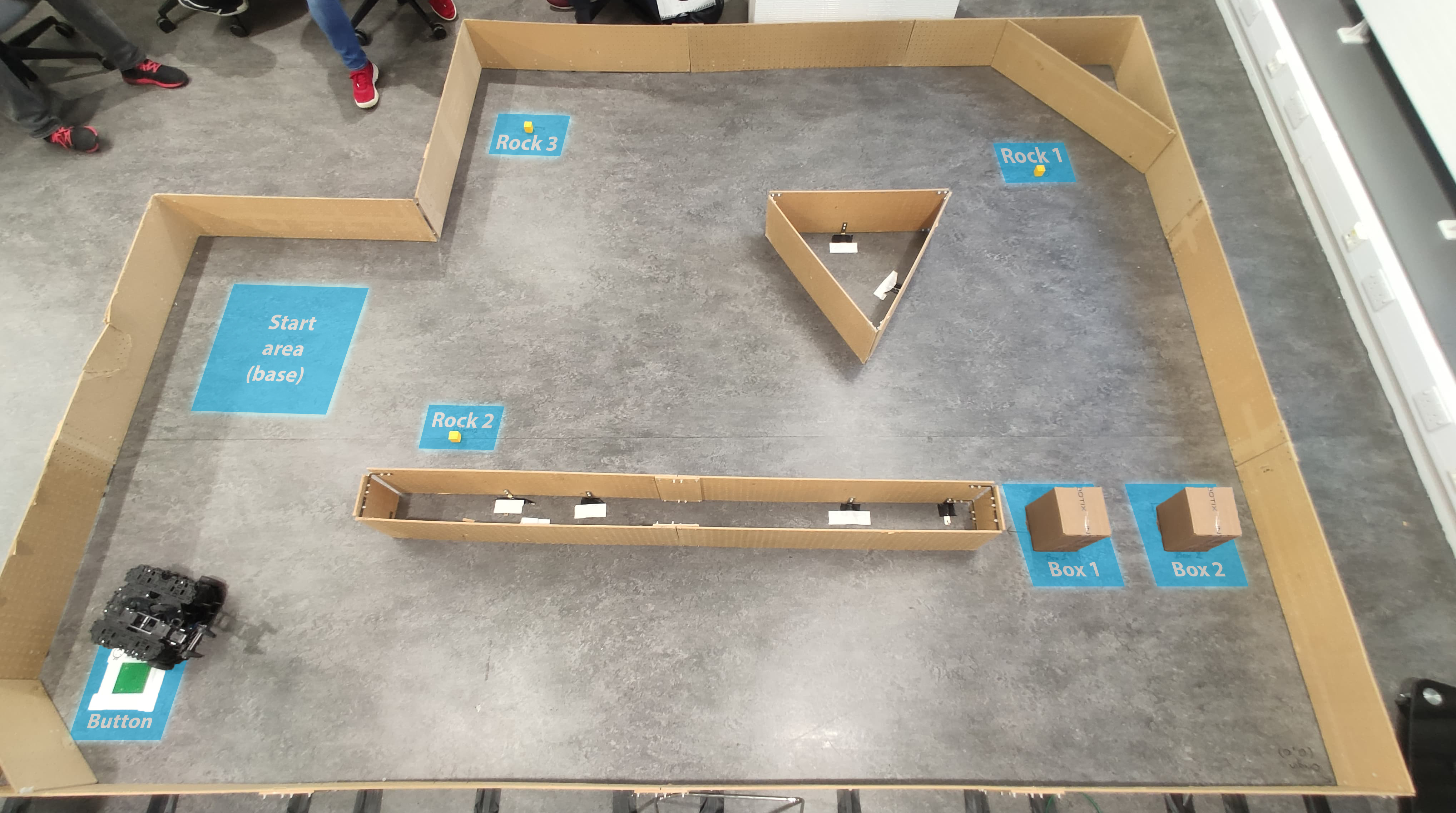
Note that due to the scope and short time span of the project, computer vision has not been used and instead has been accounted for by predefined positions of objects.
In this blog, I want to share what my teammate Alex Roy and I did and how we managed to get the most marks in this practical.
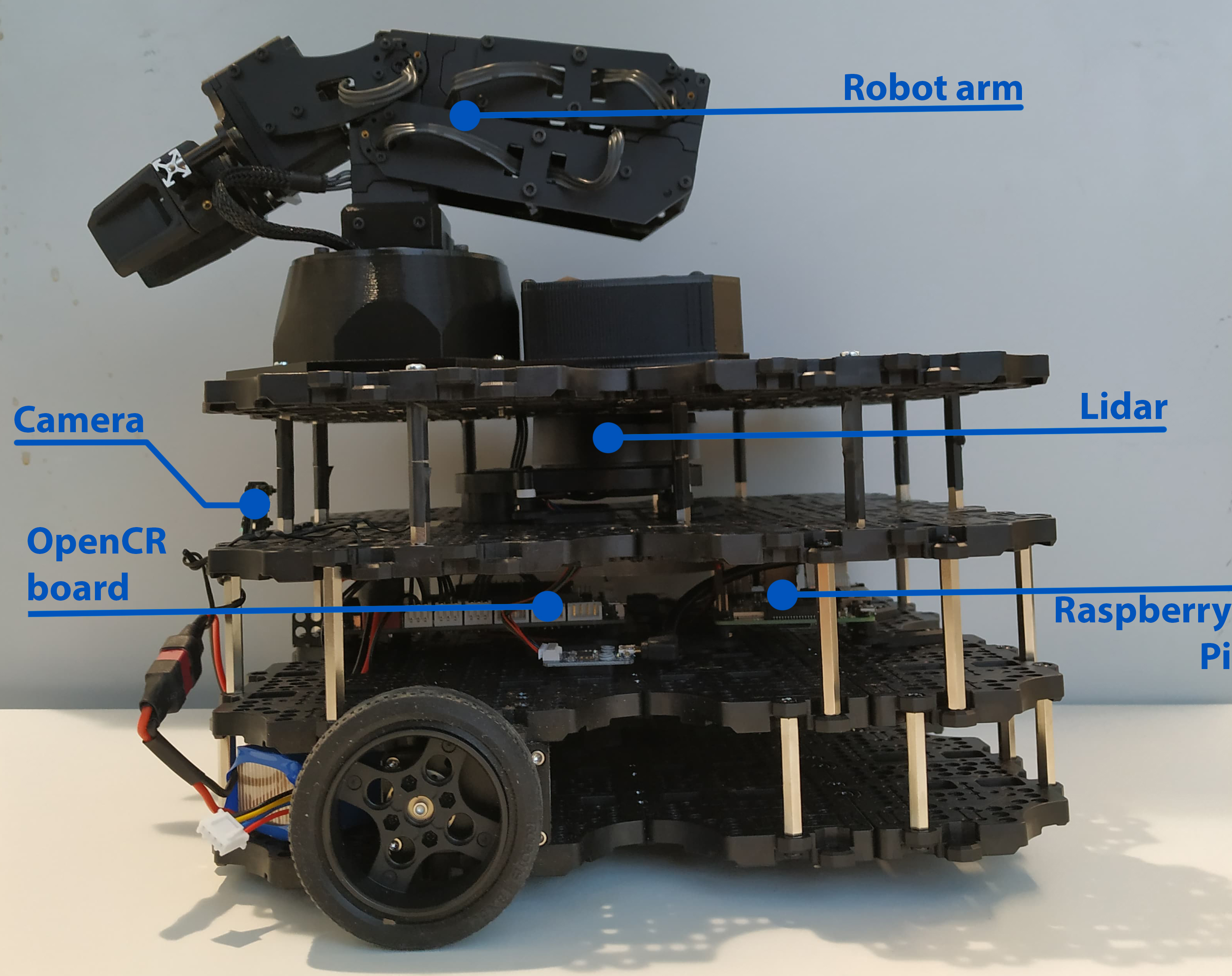
Robot
The robotic platform we used was the Turtlebot3, which is a small and affordable differential drive robot. It is equipped with 2 DC Dynamixel XM430 motors, which can be controlled independently and provide accurate wheel odometry. Additionally, the robot is equipped with a 9-axis IMU, Raspberry Pi Camera, and an LDS-01 Lidar. For computation, the robot uses a Raspberry Pi 3 Model B and an OpenCR board, which is an embedded ARM Cortex M7 controller. Additionally, the robot is equipped with a 4 degree of freedom Interbotix PX100 robot arm which is controlled with servo motors and used for manipulation and grasping objects with the attached gripper.
Software
The robot system was designed to be generic and widely applicable to a variety of tasks involving navigating and manipulation.To run the robot, it just needs predefined:
- A discrete map of the environment
- A starting position
- A list of action consisting of:
- Move - navigate to a 2D position in the map
- Arm - move end effector to a given 3D position in the map frame along with a method of moving the arm to that point.
These tasks are distributed by the high-level state machine as per the diagram below:
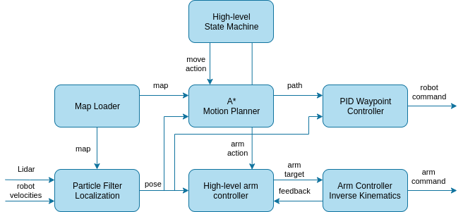
The particle filter uses the laser scans, 2D robot velocities, and the map to localize the robot with 250 particles running at 10Hz. The sensor model uses a likelihood field to find the most probable particle and a motion model, which was analytically derived from experiments with the robot. The map itself is loaded by the map loader
The motion planner is an implementation of A* in metric coordinates, which samples possible paths around the perimeter of the robot. The cost of the potential path is computed by the distance to the target and whether the robot collides with the map. Afterward, the path is sent to the PID Waypoint Controller, which goes through each waypoint using a PID controller for the angular velocities. The forward speed is then a function of angular speed.
Finally, there is the high-level arm controller which accepts 3D positions for the arm end-effector calculates intermediary arm targets and then feeds them to the arm controller, which uses analytical inverse kinematics to move the arm.
Implementation details
The whole software runs on a Raspberry Pi 3B and the Robotics Operating System (ROS). All of the software (except the state machine) is implemented efficiently in C++11 using the Eigen library for further optimizations. We are very proud of this and is best shown by the performance of the particle filter. Further, the whole stack is done using standard ROS messages and tools where possible, and we developed many data visualizations:
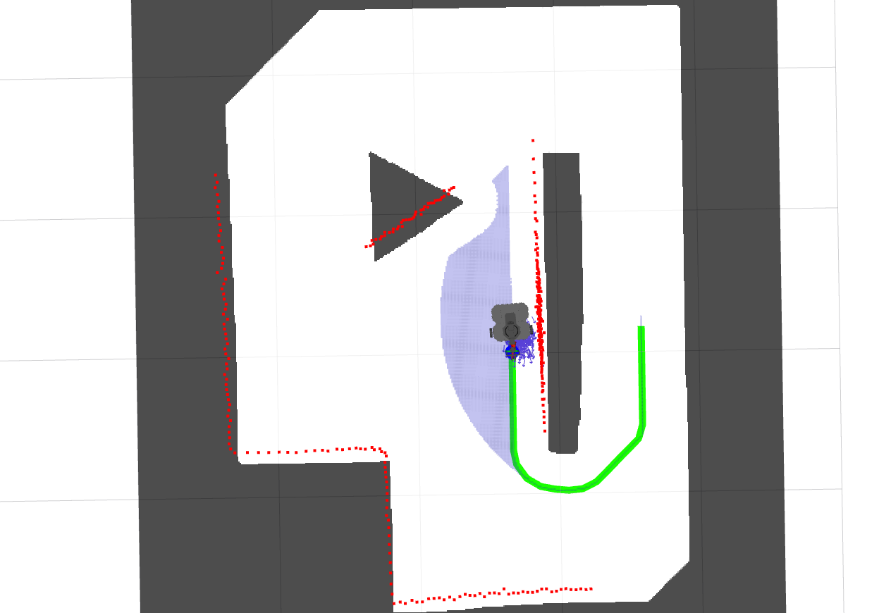
In the picture above, you can see data from one of our experiments. Here is what all of the data is:
- The map is is greyed out where there are obstacles
- The red dots are the Lidar pointcloud
- The small blue arrows are the individual particles of the particle filter
- The green path is the one found by the A* algorithm
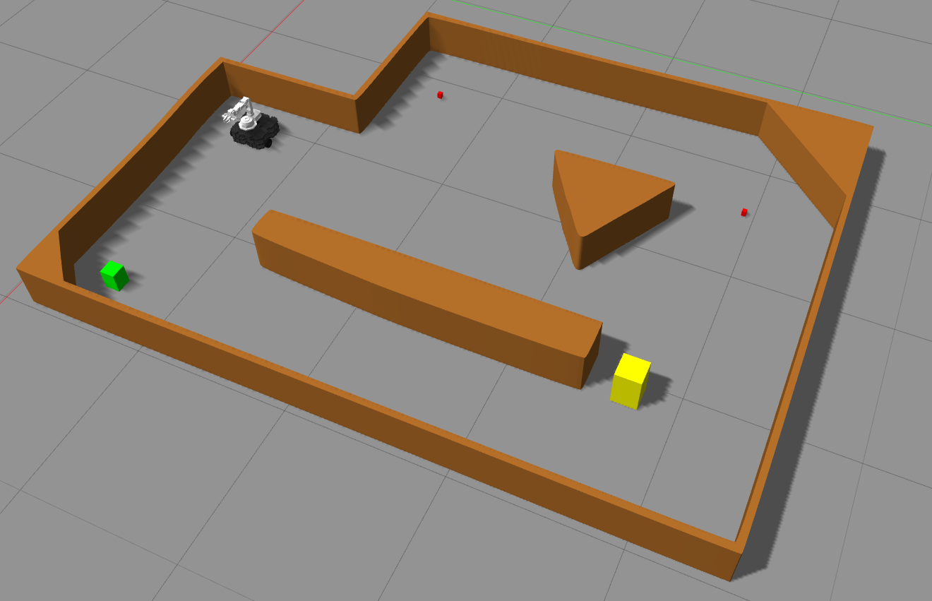
Simulation
During the development of this, we also made a crucial Gazebo simulation for the speed of our development and I would even say, we wouldn’t have won without it. The Gazebo simulation is based on the open-source models for the Turtlebot3 and Interbotix PX100 robot arm:
Further links
- The project is open-source and accessible here. You can also find setup instructions there.
- My scientific report of the project is here on my website and goes into more technical detail.
Finally, here is the robot in aciton:
(don’t mind the internet cable, the wifi broke that day)